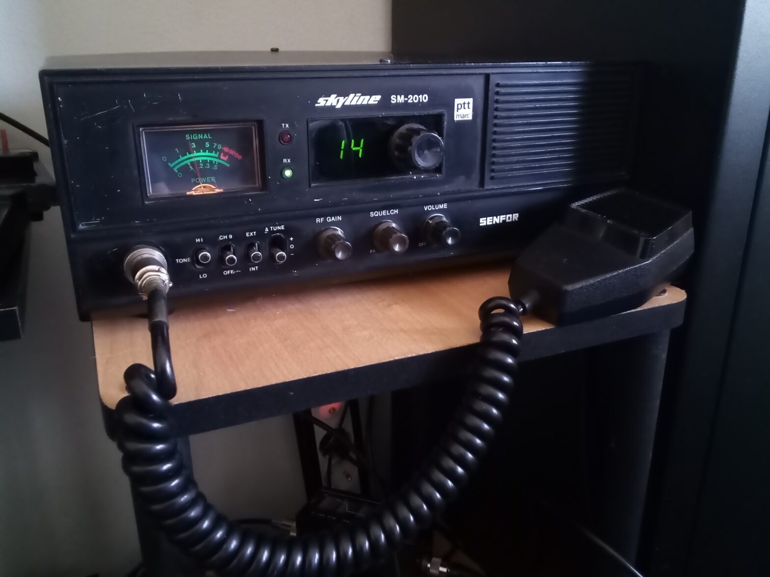
My radio adventures all started with a Skyline SM2010. This is a 22 channel CB radio made by Cybernet. The Skyline was one of the legal CB radios you could buy after it was decided to legalize CB radio’s in the Netherlands, anno 1980. I wrote a small article about this already at pttmarc.nl (in dutch).
I’m not going to repeat that story here, you can use google translate if you want to read it in English. Maybe it is nice to tell here now all of what I had broken on the radio and the story of its reparation. It’s a bit of a long story. It took me a little bit over a month to fix.
Let’s start off with a list of the things that I knew about that had problems before I started this project.
- about half of the wire frame was cut loose
- the microphone connector was removed
- the volume knob and potmeter annex on/off switch was missing
- the transistor final also missing
- there was no speaker
- there was no power cable (220 Volt)
It had more issues, but I had conveniently forgotten about that.
Here’s a few photo’s of the old radio, like it had been in the closet down here for the past 30+ years.
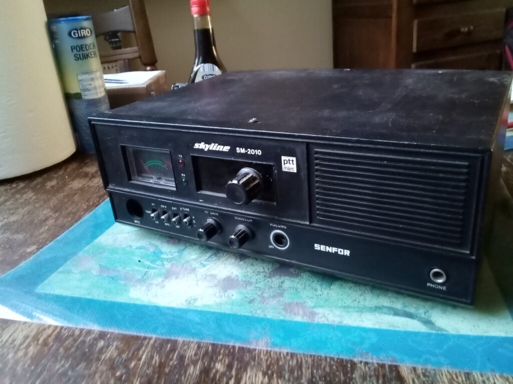
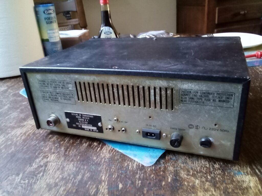
It certainly ain’t a beauty, but it was still my first CB radio.
I bought another one, in order to have a bit of a chance to success. This was a very nice one, with minor defects and not intended to loan parts from. Instead it was bought, so that I had a working version that I could look at for details and to compare measurements. I sold this good and nice Skyline pretty much immediately after my own Skyline started working again. A radio amateur that I met on Marktplaats (the dutch eBay), Henk (PD2HDX) had send me most of the missing parts from the list above for free. On top of that I also bought an old abused Audio Sonic MS-201 for a pittance. The Audio Sonic has functioned as a donor radio in case I was still missing parts that I had not already received from Henk.
Anyways, here’s the story of the repair.
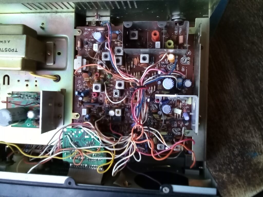
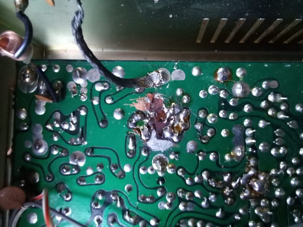
The print in the Skyline SM 2010 is a PTBM117AOX from Cybernet.
Sunday, March 19
The first thing to do was to add a power cable so that we can hook it up to 220 Volt again. The powersupply was already disconnected from the radio, so checking if the power rail worked could be done without risking additional damage to the radio.
Connected it all and … nothing. The fuse had blown. I did check the fuse before, but nevertheless I put another one in. That one also immediately blew… looked at this for a bit and at least the zener diode had a short. But there’s more wrong. If I use a multimeter and check with the zener diode removed, it still measures a short where the other radio doesn’t.
Oh well… didn’t want to spent too much time on that now as the radio can also work using an external power supply and test that way.
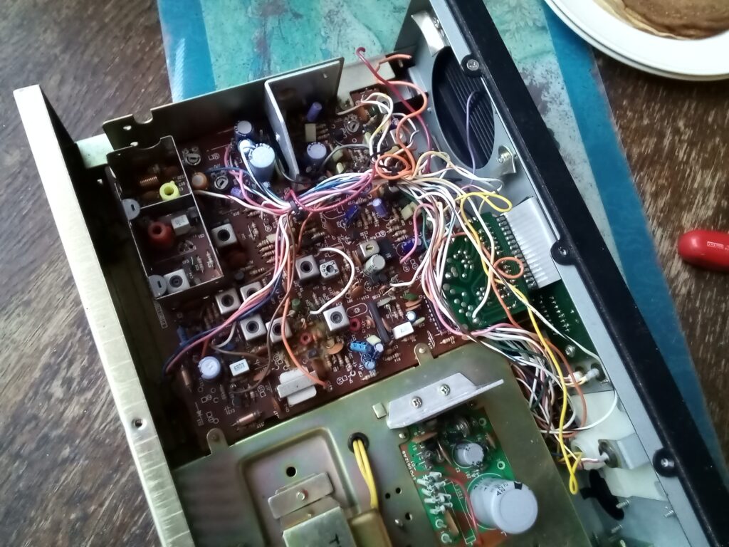
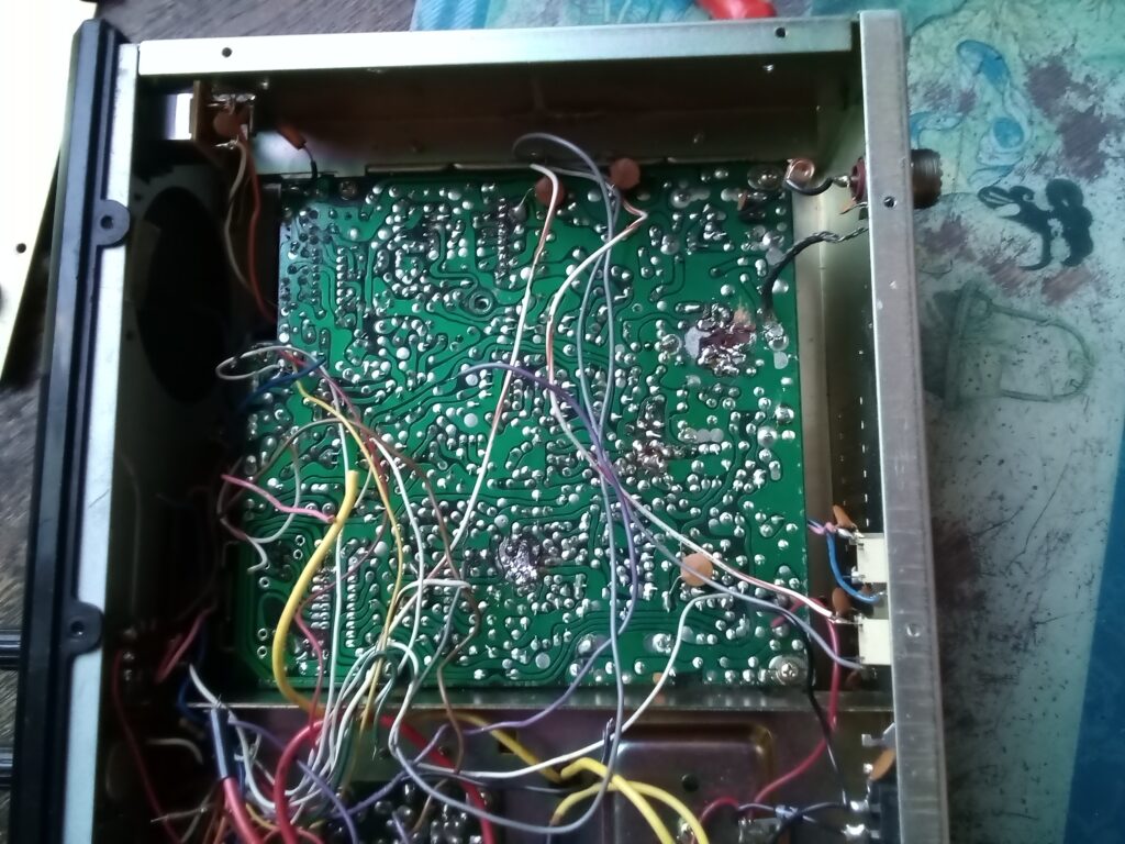
So I started by wiring the power/volume button. What a huge amount of wires??
That’s going to take some time before it is all connected.
Saturday, March 25
OK, got another evening of work in Skyline in. The more time I spent on improving the radio, the more problems appear to pop up. I did not do a half job when I was a teenager in destroying the radio!
The RF Gain and Squelsh have only 1 wire connected. The 10.240 MHz crystal is gone. The audio chip is hanging loose from the cooling plate. The ferrite core from one of the transformators has disappeared… So with the new discoveries added to the list, it doesn’t exactly feel like I made progress. But wiring up the power button is almost completely done.
The generous donor of the missing components called my Skyline a junker and he wasn’t wrong about that. But I just keep going.
Is it financially worthwhile to repair? No of course not, but I will always learn something, and then there’s the “sentimental value”. It’s a hobby, so I don’t really have to validate if it makes sense. Let’s first get the wiring harness connected. We’ll see after that, how far we’ll get. I’m hoping to be able to spent a couple more hours on it this weekend.
Monday, March 27
Well, that was an intense weekend soldering. Outside it was raining all day, so the other plans ended up getting canceled. It looks like that the whole wiring harness is done. I think that about 3 quarters of the wires where hanging loose. Then I did the rest, with the excemption of the transformator core. Just tried to test it using an external power supply.
Turned it on … and … nothing. No light bulbs, nothing visible at all, but.. the radio is drawing a hefty 3 amps nevertheless. Even with the settings on PA. So I have to track down a fault somewhere. Of course this was to be expected. Also documented a lot about the wiring harness. So I want to check that again and verify it all against the working cb radio. Perhaps I didn’t get the desired result yet, but I made progress. During the week I will receive the zener diode by post, so perhaps that allows me to fix the power supply?
Monday, April 3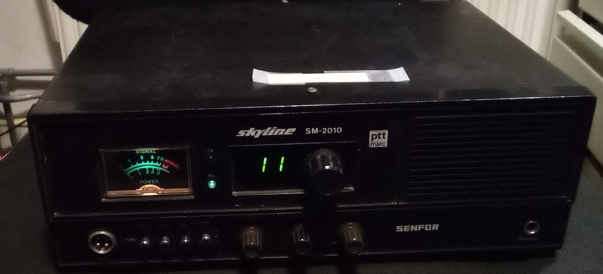
Didn’t have a lot of time this weekend. Well OK, yesterday afternoon and evening.
Just looked at it for a bit, but no real progress this evening. Yesterday wasn’t too shabby.
As you can see in the picture above, it now turns on!
This is without the internal power supply. Perhaps it works, but I only have a 1 Amp fast fuse and it blows immediately. Perhaps a slow fuse won’t..
For the rest.. I started with tuning the oscillator and around the 10.240 MHz it works fine. But if I then try to adjust the voltages for the PLL chip, it shows an instable voltage around 6 Volt instead of getting a steady voltage.
This is when on the AM/SSB Cybernet export radio’s it is time to swap the VCO block. But here we’ll have to figure out what is broken in the VCO. Probably a varicap diode that should be there somewhere.
But I now have a fresh new short in the microphone connecter and it puts me off. I compared the mic wiring with my donor radio and it’s different there. But this is also where the previous owner had been mucking with it. I’ll check it against another 117AOX cybernet radio that I still have in the shack. Maybe that one matches the Skyline.
I’ll do that somewhere during the week. Sadly I’m too busy tomorrow.
Thursday, April 6
Found the reason of the short. It was my own fault. – of course – The connector of the external speaker was loose, so I had fastened it. What I had not noticed was that the external ring should not connect to mass. But it was.. Added a little isolating rivet and another problem addressed.
After connecting a microphone, I noticed that sound wasn’t working. That is, sometimes it did work and sometimes not. Most of the time it did not.
Anyways, so much for Thursday.
Saturday, April 8
By lightly tapping with a finger all over the printed circuit board I managed to find that one of the legs of the audio chip wasn’t well connected. So… just get the soldering iron out and fix that. At least, that was the idea. Once I heated it up, the leg fell out of the print! I tried to put it back in an impromptu way, so that the leg would be connected to the chip again – with the chip still in the print – but that only resulted in a short circuit. Nothing else I can do than removing the chip.
As it turns out all of the legs on the chip had been soldered onto the chip instead of being part of the chip as one would expect. By now, I had lost 4 legs.
Well.. I added the wires for 4 new legs, soldered those directly onto the chip and put it back into the radio. That took care of it, now the audio was almost perfect.
But if I turn up the RF Gain the audio goes softer? Weird.
Sunday, April 9
Been searching for why the mixer is not having a signal on it. It doesn’t look like that it is the varicap diode. Haven’t found anything yet.
Monday, April 10
Looked at two other PTBM117AOX radios to see which one is best to keep as reference material. Both have been heavily “screwdrivered”. Kept the one with the nicest printed circuit board (stabo xm2200). It has a C2078 as final transistor, but only outputs about 50 milli watts, weird.
Saturday, April 15
This weekend I have been searching why the mixer in the VCO circuit isn’t working. Searched for a long time, eventually I figured to get my oscilloscope out and that’s when I noticed that the signal coming out of transformator T1 was the same as the signal going in.
I then compared that to how it looked like on the good Skyline and there signal out was different. Decided to remove T1 and after it was removed I noticed a very small bridge of tin between 2 print tracks that created a short. This was impossible to see with the naked eye before I had removed T1. I cleared the short and put T1 back in.
The mixer now works and now I can also start to hear another CB radio when tuned to channel 11. The signal is very very weak. The S-meter does not move and stays in the left corner. Tried to improve that a little bit by tuning T5/T6 and T7. But T5 is stuck, unable to move the core. I broke 2 trimmer adjustment tools on that. Replaced T5 with one from the junk radio and left it at the current setting. Receive is still the same. Can also transmit. But the same story, the signal is very very weak.
Sunday, April 16
Looked at the issue with the power supply again. Searched for long.. Evaporated 3 fuses. Every now and then, I measured a short circuit. Removed the component, measured it and the short is gone. Then check the component, but the component is also fine. Rinse, repeat that a few times with different components…. Eventually I notice that the voltage regulator does not have an isolation mica sheet between transistor and cooling element. As a result, it sometimes makes contact and sometimes not.
Inserted a mica sheet and it works fine.
So now only the weak send/receive issue left. I suspect that this has something to do with the RF Gain that works really weird. Putting the RF Gain to max receive just makes the radio silent. Hopefully this is the last problem 🙂
The 16 year old version of myself left a really “nice” puzzle there. The voltage regulator was connected to the cooling element with a little plastic screw, making it very easy to miss the mica sheet.
Sunday, April 23
That problem with the RF Gain?
Took me the whole weekend. 🙂 On Saturday I’ve first been looking at it for about an hour or so. Mostly checked connections, touched up some soldering connections, cleaned the print a bit, etc..
Then on Sunday I checked the wire harness again around the Squelsh and RF Gain. The reasoning behind that was that I must have made a mistake wiring things up. On the RF Gain I noticed strange voltages, 9.6V while it should be 0.6V when comparing it to the other Skyline. Spent a lot of time measuring, checking diodes, looking at the schema etc…
Eventually I came to the conclusion that transistor Q6 might be broken.
What a surprise, I removed it and measured the HFe.. 0.0 Hmmm… plus the removed transistor was a C2153 instead of the expected C1047. Hmmm.. Another surprise of teenage me? No idea… but I took the C1047 from the donor radio and put it in my Skyline. And… now the RF Gain works as normal!
In addition to that by tuning the circuits a bit I could now also receive a bit. Wow.
But transmitting is still around zero. So have been trying to tune that a bit.
Figured out that you can change the voltages for TP1 with CT2.
I now have:
at receive:
channel 1 = 4.04 V
channel 11 = 4.88 V
channel 19 = 5.67 V
channel 22 = 6.02 V
and at transmit:
channel 1 = 2.77 V
channel 11 = 3.29 V
channel 19 = 3.79 V
channel 22 = 4.01 V
I don’t know if that’s correct, but it was what I saw at the other Skyline, so I matched it.
As for the output power I now get 100mW and that’s it. But I don’t have a trimmer adjustment tool for L5/L6 so it might be that?
At least we got serious progress here!
Oh and those voltages above have been measured at TP1. I seem to be searching for the most basic things sometimes.
Monday, April 24
For transmit I now tuned T2, T3 and T4. That should be it, along with L5 and L6, as far as I know. So.. I’m going to look if I can file down a tooth brush handle to a trimmer adjustment tool for L5/L6 (Hi hi).
L5 and L6 are the red and yellow coils at the back of the power stage. Had managed to use an existing trimmer tool to adjust the yellow coil a little bit. Got a tiny bit more power. The red coil seemingly got stuck. I’ll try a little bit more, otherwise I maybe should look at the donor radio again. But it very much looks like to have solved it. 🙂
Last Sunday I had almost given up and introduced a break of a few months.
.. and the red coil just spoke and it was “crack”.. broke the core.
The donor radio also has no core in the red coil. Henk (PD2HDX) assures me that the core in the yellow coil is the same. That one is still there. He also gives me the following tip:
“Well, sometimes you have to make them movable again, otherwise these cores break very easily, especially if your trimming tool does not have the correct size. I tend to make them movable by using a metal hex key of the correct size.”
100mW is the max I can get out of the power stage… this is with the red coil completely at the bottom, just like the yellow one.
I’m going to call this a “success” and close everything up again.
This is going “to be continued” at another time. For now I’m going to play a bit with it. A small amplifier is going to solve the power stage issue for now.
OK.. so only 80mW.. I moved the core in the red coil to the top (apparently it was wrong to have it at the bottom). Later this week I will have a look at what it is doing on a spectrum analyzer.
It’s just very QRP this way. LOL
— to be continued —