This Cybernet printed circuit board was used a lot for a variety of the legal cb radio’s (PTT marc) in the Netherlands. You can find it in brands such as Senfor Skyline, Amroh, stabo, multitech, audio sonic, wipe, hycom, to name just a few.
Surprisingly there is not much info available in regards to service manuals or other tips on how-to repair these. This page collects some of the existing documentation you can find on the internet, along with tips that I have added over time while I learn more about this particular radio.
Here’s a few links to external resources (all in Dutch)
- Afregelen 27MHz Marc bakkies ptbm117aox
- PowerMod voor 22 kanalen marc bakkies
- Van 27MHz naar 29MHz
- 40 kanaals FM transceiver voor 10m (deel 1)
- 40 kanaals FM transceiver voor 10m (deel 2)
The latter few links come from a magazine called CQ-PA which has a few more articles and the archives of that can be found here: VRZA CQ-PA Archive.
Schematics can be found at the Ham International Cybernet page as well as at the pttmarc.nl schema’s page.
I won’t repeat everything in the links above apart from a few details.
First let’s start with a quick (MS Paint) drawing of the board layout.
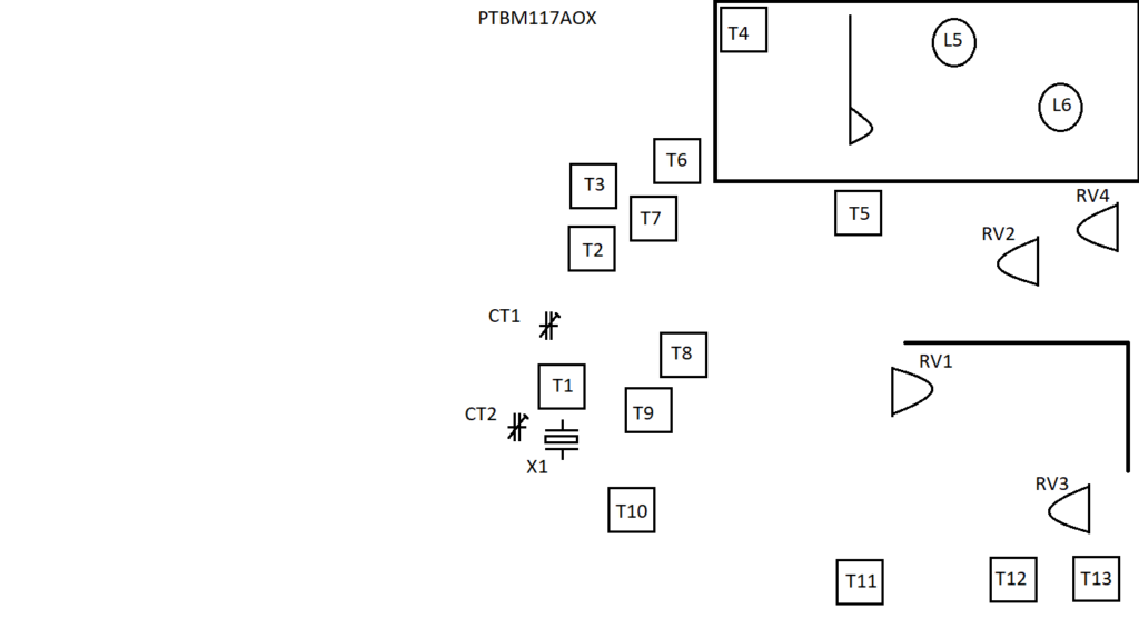
This depicts most of the transformers (T?), variable resistors (VR?) and coils (L?) that are used for tuning the radio.
Let’s name their functionality.
- RV1 = Squelch
- RV2 = FM deviation
- RV3 = RX meter (s-meter)
- RV4 = TX meter (power meter)
Receiver uses T5, T6 and T7.
T12 = tune for minimum noise level for a weak signal.
T13 = tune for minimum distortion at high LF output.
Transmitter part uses T2, T3 and T4.
The low pass filter of the transmitter consists of L5 and L6.
Set the reference frequency.
Connect a frequency counter at pin 3 on IC2. The frequency should read 10.240 Mhz. You can adjust this via CT2.
If your frequency counter uses a oscilloscope type probe with a x1/ref/x10 setting then make sure to set it at x10. This way measuring the frequency will have a smaller detune effect on the circuit.
One thing to watch out for when tuning the 10.240 MHz reference frequency is to make sure that the delta tune button is set at 0. If you have a delta tune and you have it set at + or -, then the 10.240 MHz frequency will be off when changing it to 0.
Don’t ask me how I know…
Tuning the VCO circuit.
Connect a voltmeter to TP1. You can find TP1 near R13.
Change the radio to channel 11, there should be 4.0 Volt on both transmit as well as receiving. This is the VCO voltage coming from the PLL (PLL08A). There’s two red trimmers nearby. The first one (CT2) – next to the crystal – is for setting the 10.240 MHz reference frequency. The other one combines the VCO along with T1.
If you can’t get close to the 4.0 Volt then you can adjust T1. By changing T1 and CT1 you can set the VCO voltage to 4.0 Volt for both receiving as well as sending.
After that the PLL should lock on all of the 22 channels.